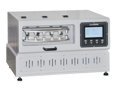
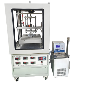
100L Thermal Shock Chamber
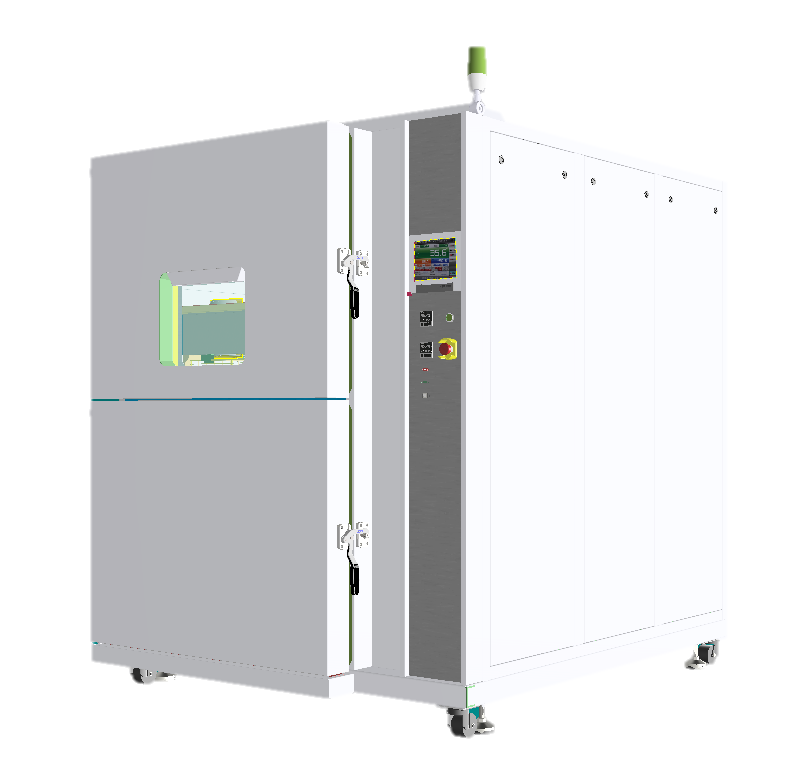


Introduction
Item | Specification |
Product Name | Thermal Shock Test Chamber |
Inner basket dimensions | 50 × 40 × 40 (W × H × D) cm |
High-temperature chamber dimensions | 65 × 70 × 105 (W × H × D) cm |
Low-temperature chamber dimensions | 65 × 80 × 105 (W × H × D) cm |
Overall dimensions | 125 × 185 × 165 (W × H × D) cm (subject to final product) |
Impact temperature range | -65 ~ 155℃ |
Test method
The basket moves vertically, and the sample moves with the basket.
Sample restrictions
This testing equipment prohibits:
(1) testing or storage of flammable, explosive, or volatile substance samples
(2) testing or storage of corrosive substance samples
(3) testing or storage of biological samples
(4) testing or storage of samples from strong electromagnetic emission sources
(5) testing and storage of radioactive material samples
(6) testing and storage of highly toxic substance samples
(7) testing and storage of samples that may generate highly toxic substances during testing or storage.
Performance indicators
4.1 Test Environmental Conditions Ambient temperature: +23°C, relative humidity ≤85%, no test specimens in the chamber (unless otherwise specified).
4.2 Test Method:GB/T 5170.2-2008 Temperature Test Equipment.
4.3 High Temperature Chamber(1) Maximum temperature: +200°C(2) Temperature change time: From ambient temperature to +180°C ≤ 35 min.Note: The heating time is the performance when the high temperature chamber operates independently.
4.4 Low Temperature Chamber(1) Minimum temperature: -70°C(2) Temperature change time: From ambient temperature to -70°C ≤ 80 min.Note: The cooling time is the performance when the low temperature chamber operates independently.
4.5 Test Zone (Basket Area)(3) Temperature exposure range: +RT ~ +155°C(4) Temperature exposure range: -55°C ~ RT(3) Temperature fluctuation: 1.0°C (expressed as ±0.5°C in accordance with GB/T5170.2-1996)(4) Temperature deviation: ±2.0°C (when ≤+150°C); ±3.50°C (when >+150°C)
4.6 Temperature Recovery Performance(1) Temperature recovery time: ≤ 5 min(2) Recovery conditions:
High temperature exposure: +155°C for 30 min
Ambient temperature exposure: Ambient temperature for 5 min
Low temperature exposure: -55°C for 30 min
Specimen weight: 5 kg aluminum (excluding the weight of the sample basket and rack)
Sensor position: Upwind side of the specimen
Water cooling: +28°C
Power supply voltage: Rated voltage
4.7 Noise≤ 70 dB(A). The noise is measured at 1m in front of the equipment and 1m in height (in a free space).
4.8 Compliant Test Methods
GB/T 2423.1-2008 Low Temperature Test Methods, Test Ab
GB/T 2423.2-2008 High Temperature Test Methods, Test Bb
GB/T 2423.22-2002 Temperature Change Test Methods, Test Na
GJB 150.3-1986 High Temperature Test
GJB 150.4-1986 Low Temperature Test
GJB 150.5-1986 Temperature Shock Test(For load, refer to 5.6.(2), passive heat load)
Structural features
5.1 Insulation Enclosure Structure(1) Wall material: Stainless steel plate 304, thickness 1.0 mm(2) Inner basket material: Stainless steel plate SUS304, thickness 1.5 mm(3) Chamber insulation material: Rigid polyurethane foam + glass fiber(4) Door insulation material: Glass fiber
5.2 Test Chamber DoorSide-latch door, 1 set
5.3 Cable HoleΦ50 mm × 100 mm oblong hole, located on the left side of the chamber, 1 piece
5.4 ColorStandard beige for the entire unit
5.5 Adjustment Feet and WheelsAdjustment feet: 6 units, for supporting the test chamber
5.6 Heaters(1) High-temperature chamber: Nickel-chromium alloy electric wire heaters, 6.5 kW × 3, 2 kW × 3(2) Low-temperature chamber: Nickel-chromium alloy electric wire heaters, 3 kW × 3(3) Heater control method: Non-contact periodic pulse width modulation, SSR (Solid State Relay)
5.7 Return Air Fan(1) High-temperature exposure: Centrifugal type, 3φ 350 W, 1 unit(2) Low-temperature exposure: Centrifugal type, 3φ 750 W, 1 unit
5.8 Drive DeviceCylinder drive device and test chamber door lock device (pneumatic drive)Cylinder: ● High and low temperature, 1 unit
5.9 Components of the Test Chamber (see attached drawings for names and functions)
No. | Name | Function |
(1) | High-temperature chamber | Used for storing heat |
(2) | Test zone / basket | The part where specimens are placed for testing |
(3) | Low-temperature chamber | Used for storing cold |
(4) | Operation panel | Includes controller, timer, over-temperature protector, over-cool protector |
(5) | Temperature recorder (optional) | Records test data |
(6) | Main power switch | Main power switch of the test chamber |
(7) | RJ45 communication interface / USB | For remote monitoring of the test chamber via centralized control software (optional) |
(8) | Chamber door exhaust button | Opens the chamber door under power-off condition without losing air pressure |
(9) | Specimen power control terminals | Controls the specimen power supply to ensure the safety of the specimen and test chamber |
(10) | Time switch | Outputs time signals |
(11) | Cable hole | For connecting specimen cables and data lines |
(12) | Electrical compartment | Installs electrical components |
(13) | Mechanical compartment | Installs the refrigeration unit |
(14) | Air inlet | Draws in outside air during ambient temperature exposure |
(15) | Air outlet | Exhausts hot air from the mechanical compartment and test zone |
Refrigeration system
6.1 Refrigeration Method:Mechanical compression binary cascade refrigeration system.
6.2 Compressor: Hitachi / Taikang compressor.
6.3 Refrigerant
High-temperature stage: R404A (ozone depletion potential = 0)
Low-temperature stage: R23 (ozone depletion potential = 0)
6.4 Cooler:Finned-tube heat exchanger, cold accumulator.
6.5 Condenser:High-efficiency water-cooled heat exchanger.
6.6 Condensing Evaporator:Stainless steel brazed plate heat exchanger.
6.7 Throttling Device:Thermal expansion valve.
6.8 Refrigeration Unit Control Mode:The control system automatically adjusts the operating conditions of the refrigeration unit according to the test conditions.
6.9 Others:Compressor return gas cooling circuit.
Electrical control system
(1) Preset Timer Function: The test chamber automatically starts and prepares for the test when the pre-set start time is set.
(2) Overheat/Overcool Protection Function: Prevents abnormal rises and falls in test temperature.
(3) Sensor Position Selection (Upwind/Downwind Side): The test temperature of the sample can be selected on either the upwind or downwind side.
(4) Stabilization Time Control Function: Timing starts when the exposure temperature is reached. The exposure time of the sample at the set temperature is the same as the set exposure time value.
(5) Exposure Time Shortening Function: Switches to the next exposure after the downwind temperature of the test area reaches the exposure temperature.
(6) Equipment Action Selection Function After Power Outage: After a power outage, the equipment action can be selected upon power restoration: Continue, Stop, or Stop after drying.
(7) Automatic Defrosting Function: Frost is automatically detected and removed before it forms inside the low-temperature chamber.
(8) Temperature Recovery Time Setting Function
The temperature recovery time can be selected, and the preheating or precooling temperature can be automatically adjusted according to the temperature recovery time setting. Whether the target time can be reached depends on the sample weight and test conditions of the test chamber.
Setting time range: 1min~20min
(9) Preset Time Display Function
The preset time for each state can be displayed in a timely manner when the target time is reached.
●Preparation end preset time
●Test start preset time
●Test end preset time
●Defrost end preset time
(10) Test Interruption Function
(11) Test End Condition Selection Function
The state of the test chamber can be selected after the test.
●Stop after drying operation
●Stop after defrosting
●Hold ready state
(12) Direction Coordinate Graph Function
The exposure setting temperature, upper air vent temperature, and lower air vent temperature can be represented graphically.
(13) Alarm Record Display Function
16 faults and alarms can be displayed.
(14) Sensor Calibration Function
The sensor control temperature can be calibrated.
(15)RS-485 communication function (optional) Two or more test chambers can be controlled through centralized management software.
Safety protection devices
8.1 Safety Protection Device List
No. | Device | Purpose | Action Content |
(1) | Earth leakage short-circuit protector (380V AC) | Personnel / machine protection | (a) |
(2) | High-temperature chamber over-temperature protection switch | Machine protection | (a) |
(3) | Low-temperature chamber over-temperature protection switch | Machine protection | (a) |
(4) | High-temperature chamber overheat protector (built-in controller) | Machine protection | (b) |
(5) | Low-temperature chamber overheat protector (built-in controller) | Machine protection | (b) |
(6) | Test zone overheat / overcool protector | Specimen protection | (c) |
(7) | Test zone overheat / overcool protector | Specimen protection | (c) |
(8) | Distribution circuit breaker (380V AC) | Machine protection | (b) |
(9) | Refrigerator high/low pressure switch | Machine protection | (b) |
(10) | Compressor built-in protector | Machine protection | (b) |
(11) | Compressor thermal protection | Machine protection | (b) |
(12) | Return air fan thermal protection | Machine protection | (b) |
(13) | Motor thermal protection | Machine protection | (b) |
(14) | Motor phase reversal / phase loss protection | Machine protection | (b) |
(15) | Compressed air pressure switch | Machine protection | (b) |
8.2 Temperature Overheat / Overcool Protectors
Used to prevent abnormal temperature rise/fall in the test zone. 1 unit each.
(1) Setting range:
Temperature overheat protector: 0°C ~ +200°C
Temperature overcool protector: -70°C ~ 0°C(2) Input: Thermocouple T input(3) Output: Relay IC contact
8.3 Earth Leakage Short-Circuit Protector
Used for main power switching, earth leakage interruption, and overcurrent interruption. 1 unit.
(1) Rated sensing current: 30mA(2) Rated current: 83A (power supply voltage: AC380V)
Standard equipment
Item | Specification | Quantity |
9.1 Cable hole | Φ50mm oblong hole, on the left side of the chamber | 1 pc |
9.2 Sample power control terminal | Sample protection, contact rating: AC250V 3AIt is strongly recommended that users use this control terminal to control the power on/off of test samples, ensuring that the circuit connected to the test samples can be reliably cut off in case of equipment failure or shutdown | 1 pc |
9.3 Power cable | 5-core (4-core power cable + protective ground wire) 3-meter cable2 cable outlet holes, located at the lower right part of the back of the chamber and the right rear corner of the top of the chamber (when facing the front of the chamber) | 1 pc |
Accessories | Load capacity: 20kg (evenly distributed) per unit | - |
1. Shelf | Shelf spacing: 10mm, can be installed with 2 layersLoad capacity: 20kg (when samples are evenly arranged) | 2 sets |
2. Cable hole rubber cover | - | 1 pc |
3. User manual | - | 1 copy |
Optional accessories (Functions)
The following accessories (functions) are priced separately and must be specifically stated in the contract or technical agreement.
Transportation
The test chamber is a single unit and will be transported as a whole.
Operating Conditions
The user shall ensure the following conditions are met:
12.1 Installation Site
The ground must be flat and well-ventilated.
No strong vibration around the equipment.
No strong electromagnetic field interference around the equipment.
No flammable, explosive, corrosive substances or dust around the equipment.
A floor drain should be available near the equipment.
The ground load-bearing capacity of the site shall be no less than 500 kg/m².
A space of no less than 600 mm shall be reserved around the test chamber for operation and maintenance.
12.2 Environmental Conditions
Temperature: 0°C ~ 35°C
Relative humidity: ≤ 85%
Air pressure: 86 kPa ~ 106 kPa
12.3 Air Source (Compressed Air)
Pressure: (5 ~ 8) kg/cm²
Connection port diameter: Φ10 mm
12.4 Power Supply Conditions
Power supply:AC380V, 50Hz, three-phase four-wire + protective ground
Allowable voltage fluctuation range: AC (380 ± 10) V
Allowable frequency fluctuation range: (50 ± 0.5) Hz
Protective grounding resistance: < 4 Ω; TN-S or TT power supply mode
The user is required to configure an air or power switch of appropriate capacity for the equipment at the installation site, and this switch must be dedicated to this equipment.
Power capacity:23 kW
Maximum current:36 A
12.5 Requirements for Storage Environment
When the equipment is not in operation, the ambient temperature shall be maintained within 0°C ~ +45°C.
When the ambient temperature is below 0°C, all residual water in the equipment must be drained to prevent water in the pipelines from freezing and damaging them.
Items excluded from quotation
(1)Handling and preparation/construction of the installation site
(2)Power supply construction
(3)Compressed air piping construction
(4) Condensate drainage construction
Quality assurance system
The company's quality assurance system is implemented in strict accordance with the requirements of ISO9001:2015.
Technical data and accessories provided
Technical data: Product certificate, operation manual, warranty card, etc.
Packaging and transportation
(1) Packaging: Transport packaging cases meeting the requirements of QB/WD008-2001
(2) Transportation: Freight
Acceptance standards and methods
(1) Acceptance standards: Technical indicators are based on the "Technical Agreement" signed by both parties; inspection methods follow those specified in GB/T5170-1995.
(2) Acceptance method: Formal acceptance shall be conducted at the buyer's site. If the buyer requires a third party (a qualified technical quality supervision department) to participate in the acceptance, the relevant costs shall be borne by the buyer.
Equipment main parts list
No. | Item |
1 | Hermetic compressor |
2 | Touch controller (Chinese/English switchable) |
3 | Circulation fan |
4 | Large heating defrosting and dehumidifying window |
5 | Door lock |
6 | Heat exchanger |
7 | Water-cooled condenser and evaporator (one set each) |
8 | Water flow switch |
9 | Leakage circuit breaker |
10 | AC contactor |
11 | Drying filter |
12 | Environmentally friendly refrigerant |
13 | Main body sheet metal (304# stainless steel) |
14 | Liquid storage tank |
15 | Solid state relay |
16 | Instruction manual, certificate of conformity |
17 | Overpressure protection |
20 | Temperature sensor |
21 | Solenoid valve |
Leave Message Get Price