Site: Home > News and events 
Universal Wear Tester UWT-300: Multi-Standard Abrasion & Durability Testing
Overview
The UWT-300 is a versatile testing system for evaluating wear resistance across textiles, polymers, and composites (ASTM D3884, ISO 12947). Designed for R&D labs and quality control teams, it simulates real-world friction, abrasion, and pilling under customizable loads and speeds.
Core Features
- Modular Testing Modes: Rotating drum (45–200 RPM), linear reciprocating (1–100 cycles/mm), and multi-directional wear simulations.
- Adjustable Parameters: Control load (5–50 N), stroke length (1–50 mm), and sample clamping force for diverse materials.
- Advanced Imaging: High-resolution cameras capture pilling, fiber breakage, and surface wear with AI-based quantification (±2% accuracy).
- High-Throughput Design: Simultaneously test up to 6 samples with automated data logging.
Applications
- Apparel: Compare abrasion resistance of denim, sportswear, and workwear.
- Footwear: Validate outsole durability under repeated impact.
- Automotive: Test seat fabrics and interior trim wear life.
Compliance
ASTM D3884, ISO 12947, JIS L1079, AATCC 119.
Optional Add-Ons
- Customizable abrasive wheels (ceramic, sandpaper, steel)
- Environmental chamber (0–60°C, 0–95% RH)
- Cloud-based reporting platform
Conclusion
The UWT-300 eliminates subjective wear assessment by delivering repeatable, quantitative data. Accelerate material innovation and reduce product failure rates with intelligent, automated durability testing.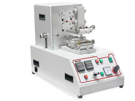
2025-04-09 10:48