Spinal Pedicle Screw-Rod Torsion Fatigue Tester


Standards:
ASTM F1717
ASTM F2706
ISO 12189
Applications:
Evaluate the fatigue life of spinal pedicle screw-rod systems with different materials and designs under torsional stress. By applying cyclic torsional loads, the tester determines how many cycles of twisting the construct can withstand before fatigue failure occurs. This allows for the comparison of different screw designs (e.g., head type, thread form), rod materials (e.g., titanium alloys, cobalt-chromium alloys), and system configurations under specific torsional loading parameters.
Study the deformation and damage of spinal pedicle screw-rod systems under long-term loading. During prolonged cyclic torsional testing, the tester can monitor the accumulation of plastic deformation, loosening at the screw-bone interface (simulated), or the initiation and propagation of fatigue cracks within the screws, rods, or connectors. This provides insight into the failure modes and degradation mechanisms under torsional fatigue.
Compare the differences in torsional fatigue performance among spinal pedicle screw-rod systems from different brands and models. The tester provides a standardized platform for objectively comparing the torsional fatigue durability of commercially available spinal fixation systems, assisting surgeons and institutions in making informed decisions based on mechanical performance data.
Provide scientific evidence for the research, development, production, and quality control of spinal implants. The data generated from torsional fatigue tests is essential for demonstrating the safety and efficacy of spinal pedicle screw-rod systems to regulatory bodies. It also supports the development of new implant designs and materials with improved torsional fatigue resistance and serves as a critical tool for maintaining consistent manufacturing quality.
Product Advantages:
The Spinal Pedicle Screw-Rod Torsion Fatigue Tester offers significant advantages for assessing the torsional durability of these complex implants:
Simulates Spinal Torsional Loading: Replicates the cyclic torsional stresses experienced by pedicle screw-rod systems during spinal rotation and movement.
Provides Crucial Fatigue Life Data: Determines the number of cycles to failure under torsional loading, a key indicator of implant longevity and resistance to fracture.
Essential for Patient Safety: Contributes directly to ensuring the long-term mechanical stability of the spinal construct, reducing the risk of implant failure and associated complications.
Supports Regulatory Compliance: Enables testing according to standards required by regulatory bodies (like FDA) for spinal implant assemblies.
Objective Performance Comparison: Provides a standardized method for objectively evaluating and comparing the torsional fatigue performance of different screw-rod system designs, materials, and manufacturers.
Facilitates R&D and Quality Control: An indispensable tool for developing improved implant systems and for maintaining consistent manufacturing quality.
Product Features:
A Spinal Pedicle Screw-Rod Torsion Fatigue Tester is a sophisticated dynamic testing system capable of applying controlled cyclic torsional loads, often as part of a multi-axis loading system that can also apply axial or bending loads to more fully simulate spinal kinematics. Key features include:
A dynamic testing frame (e.g., servo-hydraulic or electrodynamic) with capability for applying precise cyclic torsional loads. Multi-axis systems are commonly used to simulate the combined loading in the spine.
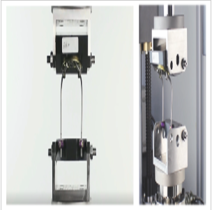
A specialized fixture designed to hold the spinal pedicle screw-rod assembly in a configuration that allows for the application of cyclic torsional loads. This fixture typically involves simulated vertebral body blocks (often made from a rigid polymer or bone substitute material, or sometimes using actual bone) into which the pedicle screws are inserted, and a mechanism to connect the screws to the rod and apply torsion.
A torque load cell for accurate measurement of the applied dynamic torsional moment.
An angular displacement sensor to measure the rotational movement of the system under torsional load.
(If multi-axis) Load cells and displacement sensors for other controlled axes (e.g., axial load/displacement).
Advanced control system capable of applying cyclic loading profiles (e.g., sinusoidal, mimicking physiological rotation) with precise control of torque and/or angular displacement, and potentially synchronized control with other axes.
A cycle counter to accurately record the total number of load cycles applied.
A data acquisition system to capture torque, angular displacement, cycle count, and potentially other axis data throughout the fatigue test.
Sophisticated software for setting up complex fatigue test parameters, real-time monitoring of test progress, detecting sample failure, and analyzing fatigue data (e.g., creating Torque-N curves, evaluating stiffness degradation).5
An environmental chamber or fluid bath designed to enclose the test setup, capable of maintaining physiological temperature (e.g., 37°C) and holding a simulated body fluid (e.g., saline solution) to replicate the in vivo environment.
Safety features such as overload protection, emergency stops, and protective enclosures.
Technical Parameters:
Dynamic Torque Capacity: (e.g., typically ranging from ±5 Nm to ±50 Nm or more, reflecting expected torsional loads in the spine)
Dynamic Axial Load Capacity (if multi-axis): (e.g., typically ranging from ±5 kN to ±25 kN or more)
Frequency Range: (e.g., up to 10 Hz, 20 Hz, or higher, as specified by the relevant testing standard, e.g., ASTM F1717. typically 5 Hz)
Torque Control Accuracy: (e.g., ±1% of set torque or better)
Angular Displacement Control Accuracy: (e.g., ±1% of set angle or better)
Axial Load/Displacement Control Accuracy (if multi-axis): (e.g., ±1% of set load/displacement or better)
Type of Loading: (Torsion fatigue, often combined with axial compression or other loads as per standards)
Maximum Number of Cycles: (Designed for long-term testing, e.g., up to 5 million or 10 million cycles as per standards like ASTM F1717 and F2706)
Actuator Stroke (Linear and Rotational): (Sufficient for applying required displacements and angles under cyclic loading)
Environmental Chamber/Fluid Bath Temperature Range: (e.g., Ambient to 40°C or higher, with precise control around 37°C)
Environmental Chamber/Fluid Bath Temperature Accuracy: (e.g., ±1°C or ±0.5°C)
Sample Size Capacity: (Able to accommodate various pedicle screw diameters, lengths, rod diameters, and construct configurations)
Power Supply: (e.g., AC 220V or 380V, 50/60 Hz, potentially with a hydraulic power unit if servo-hydraulic)
Leave Message Get Price